How to Choose the Right Bracing Formwork System?

Choosing the right bracing formwork system is a structural decision, not merely a purchasing exercise. The system must resist fresh-concrete pressure, wind, vibration, and accidental site impacts. It must also support safe access, accurate alignment, and predictable cycling. On a real wall pour, a small bracing error can appear as a leaning panel, damaged tie, or delayed crane operation.

John A. Hurd, a respected formwork specialist and author of Formwork for Concrete, described formwork as “the mold or die used to contain and shape plastic concrete until it is self-supporting.” His statement remains practical today. The formwork carries temporary forces before the concrete carries permanent ones. ACI 347R, Guide to Formwork for Concrete, stresses engineered design, load assessment, inspection, and safe erection. CIRIA Report 108 also highlights pressure, stability, and construction-stage risks. These references offer dependable foundations, but they cannot replace project-specific judgment.

Market research from Grand View Research identifies modular and reusable formwork as important trends within the global concrete formwork industry. That trend sounds efficient. It is not always efficient. A system with excellent reuse may still fail a narrow site, restricted crane plan, or demanding wall height. Contractors should compare panel dimensions, brace capacity, anchorage, adjustment range, labor needs, and removal time. They should also examine supplier calculations and installation training. Experience matters here. Sometimes, the cheapest system becomes the most expensive after one unstable pour, one redesign, or one lost working day.
How to Choose the Right Bracing Formwork System?

Define the Project Requirements for a Bracing Formwork System

Choosing the Right Bracing Formwork System

Choosing a bracing formwork system starts with a clear project brief. Do not begin with catalog dimensions. Record wall or column heights, section changes, concrete pressure, pour rates, and construction cycles. Include wind exposure, slab loading, crane limits, and available working space. These details shape the required brace capacity and anchor arrangement. Small omissions become expensive on site.

Walk the work area before selecting equipment. Measure access routes, ground levels, edge distances, and embedded items. Check the ground. A brace may fit the drawing but fail beside a trench or congested reinforcement. Discuss the pour sequence with the formwork supervisor and structural engineer. Check applicable safety rules, temporary works calculations, and approved installation procedures. An experienced team should review tie spacing, base stability, adjustment range, and inspection points. Photos and marked-up drawings improve communication.

Practical requirements also include labor, reuse, transport, and storage. Estimate how many relocations the crew can complete during one shift. Ask whether components can be handled safely without awkward lifting. Do not guess. A previous design might appear efficient, yet repeated adjustments can slow production. Allow time for trial assembly and a documented pre-pour check. Do not treat the first layout as final. Field conditions change. Review the system after each pour, especially when deflection, leakage, or access problems appear.

How to Choose the Right Bracing Formwork System?

Define the Project Requirements for a Bracing Formwork System

Before selecting a bracing formwork system, define the key project inputs. The example below shows practical requirement values for a medium-to-high concrete wall application. These factors influence panel capacity, tie spacing, brace arrangement, anchoring, and installation planning.

Higher values indicate greater design or planning demand. Final formwork selection must be verified against the structural design, concrete pressure calculations, site conditions, applicable safety requirements, and the manufacturer’s technical documentation.

Compare Bracing Formwork Types and Structural Configurations

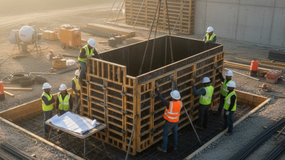
Choosing the right bracing formwork system starts with comparing how each type controls movement. Push-pull braces suit wall panels that need quick alignment adjustments. Diagonal brace frames provide stronger lateral restraint for taller pours. Tie-rod systems reduce panel spreading, but they need accurate installation and careful sealing around holes. A poor match can cause uneven joints, concrete leakage, or visible wall displacement.

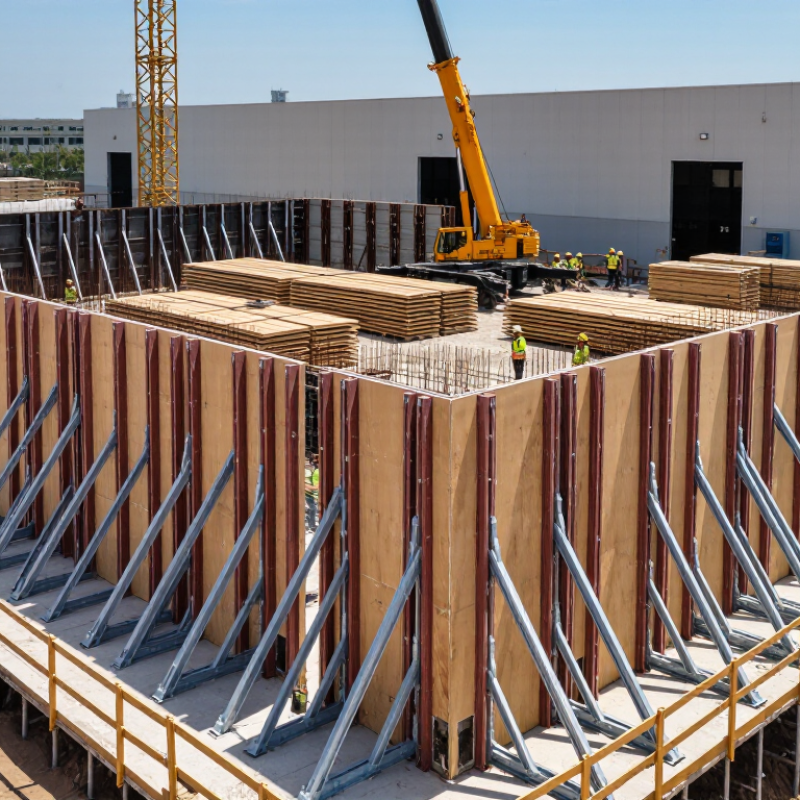
Structural configuration matters as much as the brace itself. Check wall height, panel width, concrete pressure, wind exposure, and foundation strength. A single-sided wall may require anchored braces because the opposite side cannot hold a standard tie system. For double-sided walls, opposing panels can share pressure through tie rods and walers. Uneven ground creates another problem. The brace may look stable but transfer force into weak soil. Engineers should verify load paths, anchor capacity, spacing, and working access before the pour.

Tips: Mark brace positions on the slab before assembly. Keep adjustment points reachable. Inspect pins, threads, anchors, and bearing plates. Do not rely on appearance alone. Small gaps often reveal larger alignment issues. Field conditions can defeat a well-designed layout, so record actual measurements and revise the setup when necessary. Even experienced crews can underestimate pressure during rapid placement. Local safety rules and a qualified structural review remain essential.

Evaluate Load Capacity, Stability, and Site Safety

Choosing a bracing formwork system starts with load capacity, not convenience. Fresh concrete creates vertical pressure, while placement speed, temperature, slump, and vibration affect lateral pressure. ACI 347R requires engineers to consider these changing loads during formwork design. OSHA 29 CFR 1926.703 also requires formwork and bracing to withstand anticipated vertical and lateral loads.

Check the calculations against real site conditions. A high pour rate can overload braces before workers notice movement. Confirm brace spacing, anchor strength, connection details, and allowable deflection. Small shifts matter. A 10 millimetre displacement can distort wall alignment and increase stripping risks. The UK Health and Safety Executive recorded 51 worker fatalities in construction during 2023/24, showing why temporary works need disciplined control. Formwork failures are not always dramatic. Sometimes, warning signs begin with loose wedges, bent members, or uneven settlement.

Stability also depends on the ground beneath the system. Inspect sole plates, base support, tie rods, and access platforms before each pour. Keep materials away from brace lines. A clean inspection record helps, but it cannot replace a physical check. This is where practice often falls short. Crews may trust yesterday’s inspection after rain, excavation, or a design change. Reassess the system after every significant alteration. A competent temporary-works engineer should verify the design, while supervisors confirm installation and safe access at the workface.

How to Choose the Right Bracing Formwork System? - Evaluate Load Capacity, Stability, and Site Safety

Use the following comparison as a preliminary selection guide. Final dimensions, spacing, allowable loads, anchorage, and bracing arrangements must be verified by a qualified engineer using the applicable project standards and the actual site conditions.

Bracing Formwork System Typical Application Typical Vertical Capacity Range* Lateral Stability Performance Recommended Working Height Site Safety Considerations Installation Speed Best Selection Condition
Adjustable Steel Props with Primary and Secondary Beams Residential slabs, small beams, low-rise concrete structures, and localized temporary support. 10–40 kN per prop
Capacity decreases as prop extension and eccentricity increase.
Moderate when connected with diagonal bracing and securely fixed to the formwork grid. Generally suitable for support heights of approximately 2.0–4.5 m, subject to prop design. Inspect threads, pins, base plates, vertical alignment, and bracing before loading. Do not use damaged or bent props. Fast Projects requiring flexible spacing, low-to-medium loads, and simple manual handling.
Heavy-Duty Shoring Towers Large slab pours, transfer slabs, bridge decks, high-load beams, and repetitive commercial structures. 50–150 kN per tower
The actual value depends on leg configuration, height, bracing, base condition, and connector capacity.
High when fully braced in both principal directions and tied to a stable structure where required. Commonly used for approximately 3–12 m; taller towers require engineered checks for buckling and sway. Provide controlled access, complete all diagonal braces, verify locking devices, and prevent unauthorized alteration during the pour. Moderate High load concentration, substantial pour depth, or projects needing a robust engineered falsework grid.
Modular Panel Formwork with Push-Pull Props Vertical walls, columns, cores, retaining walls, and repetitive wall construction. Primarily designed for wall-form stability rather than slab support. Panel reactions are determined by concrete pressure and tie capacity. High for vertical alignment when push-pull props, wall ties, anchors, and working platforms are correctly installed. Suitable for wall heights commonly between 2.5–6.0 m; taller walls require project-specific design. Use guardrails and safe access platforms. Check tie rods, anchors, prop footings, panel connections, and wind exposure. Fast for repetitive walls Wall construction where accurate alignment, rapid repositioning, and controlled lateral resistance are priorities.
Tube-and-Clamp Falsework Irregular geometry, congested areas, temporary access support, and structures requiring customized bracing layouts. Approximately 20–80 kN per leg in common arrangements; capacity is highly dependent on connection slip, effective length, and bracing. Moderate to high when designed as a complete three-dimensional frame with adequate longitudinal and transverse bracing. Adaptable from approximately 2–10 m; higher configurations require detailed stability and buckling analysis. Tighten and inspect every connection, control tube overlap, maintain plumbness, and provide safe erection platforms. Slower Non-standard layouts where adjustability is more important than rapid assembly.
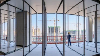
Frame Shoring System with Screw Jacks Medium-load slab support, beam soffits, podium decks, and repetitive floor layouts. Approximately 30–100 kN per frame tower, depending on frame size, tower height, jack extension, and bracing. Good when frames are vertically aligned, connected at each level, and stabilized with diagonal braces. Typically effective for approximately 2.5–8.0 m; slender towers need additional restraint. Confirm frame locking pins, jack engagement, base support, working clearances, and safe dismantling sequence. Fast Regular floor plans requiring a balance of load capacity, productivity, and adjustable height.
Engineered Proprietary-Style Modular Shoring High-rise floors, large transfer structures, bridge construction, and projects with repeated heavy-load cycles. Common design ranges are approximately 80–300+ kN per tower, but only certified project calculations establish the allowable capacity. High when the complete system, including ledgers, braces, connectors, anchors, and foundations, is installed as designed. Suitable for demanding heights and loads when supported by a documented temporary-works design. Require trained crews, exclusion zones, lifting plans, inspection records, and a formal load-release and dismantling procedure. Moderate to fast Large, repetitive, or high-risk structures where engineered performance and controlled installation are essential.

*Capacity figures are indicative screening ranges only and are not universal allowable loads. Fresh concrete weighs approximately 24 kN/m³; therefore, hydrostatic pressure can approach 24 kPa per metre of concrete depth before accounting for placement rate, temperature, vibration, admixtures, and formwork friction. Check vertical loads, lateral concrete pressure, wind, impact, uneven settlement, buckling, connection slip, and foundation bearing capacity before construction.

Check Compatibility with Construction Methods and Site Conditions

How to Choose the Right Bracing Formwork System?

Check Compatibility with Construction Methods and Site Conditions

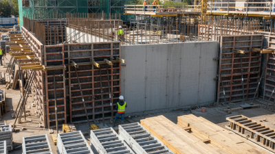
A bracing formwork system must match the construction method, not only the structural drawings. For cast-in-place concrete, check pour speed, wall height, vibration loads, stripping time, and reuse cycles. For climbing or phased construction, confirm anchor locations and lifting access before delivery. A system that suits a flat urban site may perform poorly on uneven ground.

Site conditions deserve equal attention. Measure crane reach, working-platform width, wind exposure, ground bearing capacity, and access for concrete pumps. Rain can soften access roads. Tight corners can prevent panel movement. These details sound ordinary, but they often control productivity. The McKinsey Global Institute’s 2017 construction report found construction productivity had grown by about 1% annually over two decades, far below manufacturing’s 3.6%. Poor coordination remains one practical cause.

Safety checks must follow the design basis and local requirements. The U.S. Bureau of Labor Statistics recorded 1,069 fatal work injuries in construction in 2022, with a fatality rate of 9.6 per 100,000 full-time workers. That figure is not specific to formwork, but it shows why temporary works need disciplined control. Verify load paths, ties, braces, platforms, and inspection points against applicable standards, such as ACI 347R or EN 12812. A neat layout can still fail in practice. Recheck it after weather changes, sequence changes, or equipment substitutions. The overlooked detail is often the expensive one.

Select the System Based on Cost, Reuse, and Installation Efficiency

Choosing a bracing formwork system starts with more than its purchase price. On active sites, compare rental, transport, labor, cleaning, and storage costs. A cheaper frame can become expensive when crews need extra adjustments. Review the concrete geometry, pour sequence, and available lifting equipment before requesting quotations. These details expose costs that spreadsheets often miss.

Reuse changes the calculation. A durable system may serve many pours, but only when panels remain aligned and connections resist repeated handling. Ask for realistic reuse figures under your concrete pressure, rather than optimistic catalogue estimates. Inspect corners, ties, and braces after every pour. Small damage matters. Replacing one connector is easier than correcting a leaning wall, although this discipline requires time that busy teams sometimes ignore. Keep a simple log of pour counts, repairs, and cleaning hours. It gives later estimates evidence instead of guesswork.

Installation efficiency depends on the crew, not only the equipment. Systems with fewer parts can reduce training and crane movements. However, lighter components may demand more bracing or manual alignment. During a trial assembly, measure the time from unloading to a plumb, fully secured panel. Record interruptions, missing hardware, and rework. A project engineer should verify stability, tie spacing, and load assumptions before each use. These checks protect quality and workers. A fast setup can still lose its schedule when preparation is rushed.